Warning: This circuit can produce very high Voltages
Several years ago friend requested an inverter design for use in old tube car radios, This individual collects Nash Metropolitans and likes to keep the cars as stock as possible, this includes retaining the tube radios. These radios usually fail due to a shorted buffer capacitor, this part failure burns out the power transformer and vibrator All that is necessary to revive these radios is a working high voltage power supply. An inverter using mostly Radio Shack parts was designed. This inverter circuit is called “universal” because it can used with almost any transformer with a center tapped winding. No modifications to the transformers are necessary Many of us remember spending hours filing slots in the cores of transformers to provide room for feedback windings to turn filament transformers into flux oscillators. Because the frequency of oscillation of this circuit is controlled by an RC time constant and not by core saturation as in flux oscillators there are no large current spikes imposed upon the transistors and supply bus at switching times. Filament transformers and audio output transformers work well with this circuit, A 2 amp 18 volt to 120 volt transformer was used for the car radio power supply. With 14 volts in and a bridge rectifier and filter capacitor on the 120 volt side, the inverter output was 148 volts at 75 ma. with a 1962 ohm load.
Circuit Description
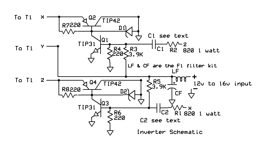
Transistors Q1 and Q3 operate as a classical RC coupled multivibrator. The frequency of oscillation is controlled by the RC time constants of C1 R2 and C2 R1. Resistors R4 and R6 provide a discharge path for capacitors C1 and C2 during the off cycle and limit the reverse voltage across the base emitter junctions of Q1 and Q3. thus preventing avalanche of the junctions. Resistors R4 and R6 also form voltage dividers with resistors R3 and R5. This voltage divider provides a small amount of bias at turn on to start the inverter. A small amount of power would be produced if a center tapped transformer were connected to the collectors of Q1 and Q3 The power output in this configuration would be limited by the small amount of base drive provided by the timing components C1 R2 and C2 R1. Transistors Q2 and Q4 operate as emitter followers, multiplying the collector current of Q1 and Q3 by the beta or current gain of Q2 and Q4. Resistors R7 and R8 pull the base emitter voltages of Q2 and Q4 to zero during the off cycle, this speeds up turn off and prevents excessive leakage. The Zener diodes DI and D2 prevent voltage spikes from killing the transistors. The transformer in an inverter can and will act just like an automotive ignition coil. When a transistor in an inverter switches off it is just the same as opening the points on an ignition system. The magnetic field will rapidly collapse producing a high voltage spike.
This high voltage spike must be clamped at a voltage below the break down voltage of the transistors or the transistors will be destroyed. This voltage spike will not be clamped by a load on the secondary of the transformer due to leakage inductance. The Zener diodes cause the transistors to turn on at a voltage below the transistor break down voltage. This will clamp the voltage until the energy in the spike is dissipated. A36 volt zener chosen for use in this 12 volt system. Zener diodes Dl and D2 should be soldered directly to the collector/base leads of Q2 and Q4. Transistors Q2 and Q4 must be mounted on a heat sink. The collectors of these transistors are connected to ground so they may be screwed directly to a heat sink with no insulating hardware. The collector of Q1 may be soldered directly to the base of Q2 and the emitter of Q1 to the collector of Q2. These leads match up if one transistor is placed with the collector tab down and one with the collector tab up. A Radio Shack filter kit was used on the D.C. input to the inverter. This filter performs several functions, it attenuates switching noise on the power supply line, it protects the inverter from high voltage spikes on the power supply line ( this is very important in automotive applications), and the filter capacitor exhibits a low A.C. impedance to the inverter.
The component values given are for an automotive application. The voltages in a cars electrical system can vary from 12.6 volts with the engine off to over 15 volts with it running. With the part values given in the parts list, the inverter will at start at 11 volts and is safe for operation up to 16 volts. If this circuit is to be powered by voltages higher than 16 volts some changes should be made. The voltage appearing across the off transistors will be twice the supply voltage so the voltage rating of all transistors should be at least twice the supply voltage plus 10 volts. The protective Zeners voltages ( D1 & D2 ) should be a minimum of 5 volts greater than twice the supply voltage and 10 volts less than the transistors voltage rating. The value of resistors R3 and R5 should match the supply voltage. Calculate the value of R3 and R5 using the following : R=(V-.6)/.0029 R=(V —.6).0029 where R equals the value of R3 and R5 and V equals the input voltage to the inverter. Where R equals the value of R3 and R5 and V equals the input Voltage. This circuit may be used in a vehicle with a positive ground or with the heat sink positive by making the following changes:
- Exchange the PNP and NPN transistors.
- Reverse the polarity of the Zener diodes.
- Reverse the polarity of the input filter capacitor.
- Reverse the polarity of capacitors labeled C5
Additional Information
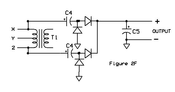
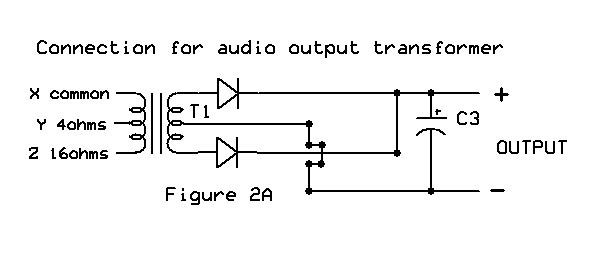
Please note that with all transformers listed, the usual primary and secondary roles are reversed. The low voltage winding is connected to the inverter circuit thus becoming the primary. This circuit inputs much more voltage across the primary windings of T1 than the transformers rating at its design frequency. A good example of this is the Radio Shack 273—1352A and the Halldorson B5—859. If the inverter is powered from 14 volts then almost 14 volts will appear across one half of the primary. The oscillation frequency of the inverter must be raised to prevent saturation of the transformer core. The operating frequency of the circuit may be changed by changinq the value of C1 and C2. See the parts list. The component values listed in the parts list will provide a switchinq frequency high enough so none of the transformers listed will be saturated when running with a 15 volt input. Power may be pulled from the primary side of the transformer. The primary side will provide plus 21.9. 25 and minus 22.3 volts if connected as shown in figures 2D, 2E, and 2F. The total power output of the inverter should be limited to 50 watts or the wattage rating of T1
This inverter drives the transformer with a square wave which has very fast rise and fall times. Some old 60 Hz transformers may run hot when driven with a square wave due to iron losses. All Radio Shack transformers listed and audio transformers seem to have ” fast enough iron ” to run at their rated current with out overheating. Figures 2A through 2F show the many output circuits which may be used. Figures 2A through 2C take the output from the secondary winding of the transformer and will produce some high voltages. The outputs from circuits 2A through 2C are isolated from the inverter and battery circuit so that either the plus or minus output may be grounded. The ground. Outputs from circuits 2D, 2E, and 2F are referenced to inverter ground or heat sink. When used as a power transformer an audio transformer Audio transformers may be operated at a power rating twice its audio rating. Capacitor C3 should have a rating of 8 to 47 uf and a working voltage of at least 10% greater than the expected output. The diodes used in Figures 2A through 2C should have a rating of 1 amp and a piv of triple the expected output voltage A bridge with similar ratings may also be used. The diodes used in Figures 2D through 2F should have a rating of 4 amps of at least 6 amps and a piv of 100 volts. Capacitors C4 and C5 and a piv of at least 100v. Capacitors C4 and C5 should be 1000uf at 50v.
Test results with various transformers
Tests performed at 14 volts.
| TRANSFORMER | WINDINGS | C1 & C2 | LOAD | OUTPUT | INPUT CURRENT |
|---|---|---|---|---|---|
| Radio Shack 273-1515C Figure 2C | 120v to 18v CT 2 amps | 1uf | 1962 ohms | 148v 75ma | 1.25 amps |
| Radio Shack 273-1515C Figure 2D | 120v to 18v CT 2 amps | 1uf | 25 ohms | 25v 1000ma | 2.39 amps |
| Radio Shack 273-1515C Figure 2E | 20v to 18v CT 2 amps | 1uf | 25 ohms | -22.3v 892ma | 2.14 amps |
| Radio Shack 273-1515C Figure 2F | 120v to 18v CT 2 amps | 1uf | 25 ohms | 21.9v 876ma | 2.1 amps |
| Radio Shack 273-1512B Figure 2C | 120v to 25.2v CT 2 amps | 1uf | 650 ohms | 97.5v 150ma | 1.5 amps |
| Radio Shack 273-1352A Figure 2C | 120v to 12.6v CT 1.2 amp | .22uf | 1960 ohms | 166v 85ma | 1.71 amps |
| Radio Shack 273-1352A Figure 2C | 120v to 12.6v CT 1.2 amp | .22uf | 1960 ohms | 166v 85ma | 1.71 amps |
| Triad F-40-X Figure 2C | 115v to 26.8 CT 1 amp | 1uf | 650 ohms | 79v 121ma | 1 amp |
| Halldorson B5-859 Figure 2C | 117v to 5v CT 3 amps | .68uf | 9740 ohms | 536v 55ma | 3.13 amps |
| Harmon Kardon 60+ watt audio output Figure 2B | 6K plate to plate to 4,8,and 16 ohms | 1uf | 1966 ohms | 282v 143ma | 4.1 amps |
| Harmon Kardon 60+ watt audio output Figure 2A | 6k plate to plate to 4,8,and 16 ohms | 1uf | 491 ohms | 133v 270ma | 3.83 amps |
Electronic Parts List
| Part | Value | Radio Shack # | Comments |
|---|---|---|---|
| C1 & C2 | .22uf | 272-1070 | Use for transformer 273-1352A |
| C1 & C2 | .68uf | No RS # | Use for transformer B5-859 |
| C1 & C2 | 1uf | 272-1055 | Use for all other transformers |
| D1 & D2 | 36v 1watt Zener | 2ea 276-564 15v Zener, 1ea276-561 6.2v Zener | Connect all 3 in series |
| F1 | 4amp power filter | 270-030A | |
| Q1 & Q3 TIP31 | 276-2017 | ||
| Q2 & Q4 TIP42 | 276-2027 | ||
| R1 & R2 | 820ohms 1watt | ||
| R4,R6,R7, & R8 | 220ohms 1/4watt | ||
| R3 & R5 | 3900ohms 1/4watt | ||
| T1 | Select to provide desired output | ||
| Output rectifiers | See text | ||
| C4 & C5 1000uf 50v 272-1047 | |||
| C3 | Capacity and voltage determined by use |


Additional Notes
Circuit 2F was intended to be a voltage doubler but it did not work that way because transformer terminals X and Z do not go negative only to ground. To get more voltage from this circuit reverse the polarity of capacitors C4 and connect the anodes of the two grounded diodes to transformer terminal Y This should produce greater than 32 volts. This has not been tested so I cannot say for sure it will work.
