Moon Light Bounce is not a 1930s, 1940s big band tune. It is not a cross between Moonlight Serenade and Jersey Bounce.
NEW: I received an Email from Gary Jarrad of Adelaide, South Australia suggesting an interesting experiment. He suggested taking the sensor out on a cloudy night and looking at reflections from the clouds. I took the sensor, filter box, and the boom box out in the garage on a rainy night. I set the sensor up just inside the garage and aimed it outside through the door at a heavy cloud cover. The system was first tested by aiming sensor at a distant streetlight that I could see. When the streetlight was focused on the photo cell, the boom box let out a loud roar letting me know every thing was still working. When looking at the cloud cover with the filter box in the “flat” mode (no filter) I just heard white noise. When the box was switched to “filter” I could hear a distinct hum when peaked up at 120cps, I was surprised to hear another but weaker peak at 180cps the third harmonic. This is a small town and all the streetlights are within two miles of each other, also they are all of the same type so I would expect the bright and dim cycles of all be in phase. At least my original idea worked sort of. Thank you Gary
The following was submitted to the W7ECA (GFAARC) amateur radio club forum.
10-04-2012
This submission has little to do with ham radio but I hope it will be of interest to experimenters This proposed experiment would find if it is possible to detect the power line frequency of city lights reflected from the moon. An article in Discover magazine July/August issue called “ Bright Lights, Alien City “ brought this experiment to mind. The article brought up the possibility of detecting alien civilizations by looking for city lights and being able to determine if the light originated on the planet or was reflected from its star(sun). The following letter was submitted to Discover magazine some time ago and I have not heard from them so I thought I would submit this to the new experimenter section of the forum.
09-2-12
Editor, Discover Magazine
While reading the article “Bright Lights, Alien City” in the July/August issue, another test for alien city lights occurred to me. Any society which has progressed into the electrical age for more than a few years would probably be powering their lights with AC. Some AC powered lights exhibit flicker (change of brightness) at a rate twice the AC frequency. It might be possible to detect a light variation of constant frequency from a distant star with good optical. electrical, and software filtering. A problem could be caused by phase shift between lights due to the distance between lights, type of lights, power factor correction and many other things. If lights were out of phase the flicker would be canceled. Optical pre filtering would help cut out much of the light of the star being observed. A very narrow optical filter which would pass a strong spectral line of some of the best light producing elements such as sodium, mercury, xenon, neon, and any other element which could produce light in an arc system would improve the signal to noise ratio. What an alien would consider light would depend upon the color of their star and what frequencies their atmosphere would pass. What would appear to us as a bright spectral line might be invisible to an alien. A electrical sweep from 10Hz to 500Hz would probably be required to catch the aliens grid frequency. In the early days before 60Hz and 50Hz became standards, we used every thing from 16Hz to 130Hz. A quick and easy test would be to focus a new moon on a photo cell, put the output through an amplifier and filter and then to a frequency counter. If an output could be detected at 100Hz(50Hz grid) or 120Hz(60 Hz grid) it would be a starting point for development of a more sensitive instrument. If a moon test did not work then it would probably not work on distant worlds.
I am putting together an experiment to see what I can hear. A cheap 4” magnifying glass has been mounted on a board and set to focus the moon on a detector holder into which I can mount various detectors. I will try a photo transistor first. I also have several CdS cells and some solar cells. No electronics have been built yet but I intend to build a low noise Fet preamp feeding an opamp filter tunable from 40Hz to 400Hz. The pre amp and filter will be powered from batteries to keep the noise down and the filter output sent to a boom box so that I can hear what is going on.


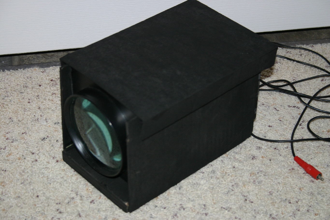


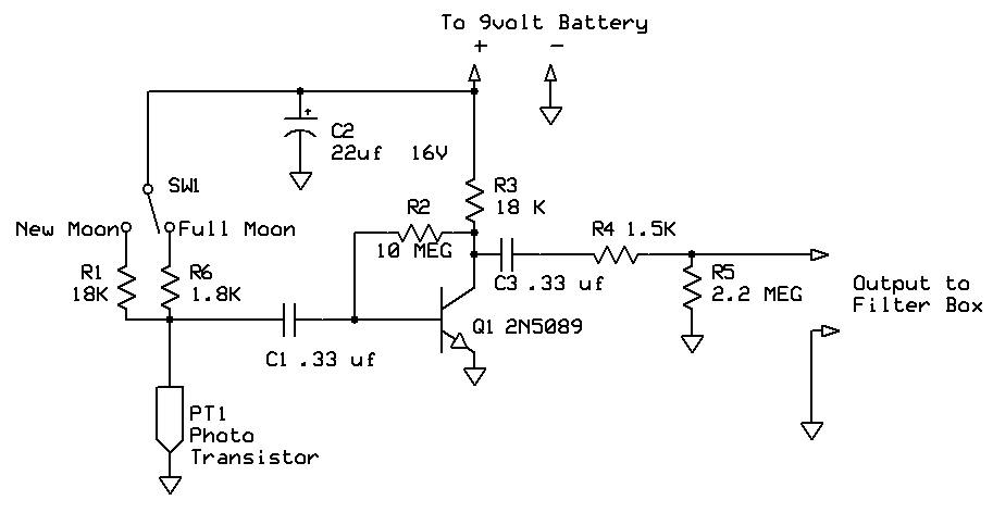
Photo transistor sensor board
02-10-13
The photo transistor sensor board has a pre-amp on the board. Power was needed to operate the photo transistor so it was easy to incorporate an amplifier on the sensor board. The photo transistor sensor was built on a one sided copper clad circuit board which provides electrical shielding and also a ground plane for the circuit. The photo transistor(PT1) was purchased from All Electronics catalog #PTR-1. The part was made by Ledtech part #LT9593-91-0125. A 9volt battery is mounted on the lens sensor assembly to power the sensor board and is independent of the pre-amp filter box. The filter box has its own battery so there is no power supply interaction between the two. Resistor R1 is the load resistor for the photo transistor. Its value was chosen to equally divide the 9volt power supply under ambient light conditions in the work area (4.5 volts across the photo transistor, 4.5volts across R1). C1 isolates any DC component at the sensor from the input to the transistor and passes AC. C2 bypasses any AC component on the power supply to ground, it is probably not necessary because the power supply battery is not shared by any other circuitry I put it in because it made me feel better. Better to start with good bypassing and not have to add it later. The amplifier transistor is a 2N5089 a low noise high gain type, the Beta of the one used was 820. The 10Meg bias resistor R2 was connected to the transistor collector rather than to the 9volt supply. This connection provides neg. feedback and keeps the operating point stable with power supply and temperature variations. R3 is the collector load for the transistor. C3 removes DC from the output line. R4 assures the stability of the amplifier when driving several feet of co-ax. R5 returns the output to 0volts DC. The amplifier shows a voltage gain of 170. During initial testing with the sensor board laying face down on the work bench several volts P to P was observed at the output. Light from a 60 watt incandescent lamp 10 feet away was leaking in the back end of the photo transistor. With R1 at 24k The sensor works well in indoor light, when the sensor is held in a window the outdoor light is bright enough to saturate the photo transistor. Initial testing on the moon will be performed with 24k in the R1 position. A full moon will probably be so bright as to require a lower resistance in the R1 position to prevent saturation.
02-21-13
All of the electronics and sensor were hauled out to the front porch to do a test with the moon. It was the first clear night in some time and we were leaving on vacation the next day so it was time. At all times there was much 120hz hum from light leakage from street lights and landscaping lights. It was not a full moon but it was fairly bright and when it was focused on the photo detector it became saturated and all noise from the system went away just as if it had been turned off. I thought I would have to lower the value of R1 to keep the photo transistor out of saturation and this turned out to be true. I will temporally replace R1 with a POT and place a voltmeter across the photo transistor. With a full moon focused on the transistor the POT will be adjusted to indicate 2 volts across the photo transistor. The POT resistance will be measured and a fixed resistor of close value will be added to the circuit board to replace the 24K resistor now in the R1 position. While testing the filter was switched out of the circuit and with the moon focused at the edge of the photo transistor ( just below saturation) .a lot of white noise was heard. The sun reflecting off of the moon was very noisy as was expected. With the filter switched out the pre-amp/filter box has a frequency response 3db down from 30hz to 27khz from the photo detector board to the boom box.
03-28-2013
A SPDT switch was added to the photo transistor board to select bias/load resistors for the photo transistor. See the schematic for the modified photo detector board. R1 18k for low light inputs such as a new moon and R6 a 1.8K for high light conditions such as a full moon. With the switch in the 1.8K position the sensor board is not saturated when pointing it outside during a sun lit day as previously noted. The sensitivity is greater with the switch in the 18K position. While the photo transistor board was apart for modifications, The input impedance to the 2N5089 amplifier was measured. The input impedance was 34K, pretty high for a common emitter amp. Oh the wonders of very high beta transistors and their high value bias resistors.
Pre-amp Filter box
03-29-13
The pre-amp input section provides a high input impedance so as to not load the sensor output. It has an input impedance of greater than 2Meg. The output impedance is low in order to drive R6 the 20K gain pot. The voltage gain of the Q1 Q2 preamp is only 1.1 and serves mainly as an impedance matching stage. The input FET Q1 a 2N4302 is configured as a common source stage followed by an emitter follower stage a 2N5210. C11 isolates the inputs from ground reference to the filter opamp and permits the feedback resistor R11 to set the DC operating point of the summing junction pin 2. The opamps are a dual unit a 1458. The first section acts as an amplifier or as narrow band pass filter. With the switch in the flat position all frequencies from 30Hz to27Khz are passed from input to output with a gain of 7.5 .Both op amps are referenced to 1/2 the power supply battery or 4.5volts by resistors R9 and R10. the opamps think 4.5volts is ground and that they are operating with + and- 4.5volts. The second opamp operates as a limiter to produce a square wave output to drive a counter. The limiter has no feedback resistor so the gain is the open loop gain of the amplifier. A 5volt zener diode in the feedback loop lowers the gain to almost zero when the diode conducts .6volts forward and 4 volts when zenering.(a 5 volt zener has a very sloppy knee at low currents and starts to conduct at 4volts). C10, R17, and a Ge diode in the output of the limiter give an output that looks like the output of a TTL logic gate and is a suitable input for my frequency counter. The output is not the best square wave I have seen because the 1458 opamp has a slew rate of only .5volts/micro sec. With the input switched to the first opamp in the filter position, a Hall network is switched into the feedback loop turning the amplifier into a narrow band tunable filter. Capacitors C6,C7,C8,Resistors R11, R12,R13,and R14 make up the Hall network. With the switch in the flat position R11 remains in the feedback position.
04-07-13
There were some problems with the pre-amp/filter board. these problems were caused by trying to cram too many parts into a too small of an area. It turned the circuit board into a blivit. I tried to get by cheaply and build everything with parts I had on hand. I should have ordered a much larger metal box to house the circuit board and used a much larger board. By using a plastic box and not leaving room for shielding some stability problems were created. The input section initially had a 10uf capacitor bypassing source resistor R2. This gave the input section a voltage gain of 11 from the input jack to the output of the 2N5210 emitter follower. With this gain and high input impedance this stage picked up much hum from surrounding wiring. The first Band-Aid was to wrap aluminum foil around the outside of the plastic case and ground it to the front panel. This got rid of the hum pickup. This stage also had a tendency to break into oscillation. Due to the close spacing on the board and wires from the pots and switches there were many feedback paths. A poor choice of part values for C2 and R4 probably also contributed to the oscillation problem. An easy fix for this stage was to remove the 10uf bypass from around R2. The removal of the bypass capacitor lowered the voltage gain of this stage from 11 to 1.1.
There was not room on the circuit board for two op-amps so a dual unit, a 1458 was used. This caused a problem when using one as a high Q filter and the other section as an open loop limiter. Although the specs on these amps show good isolation there is a small amount of interaction. The two amps share common power pins and in some cases internal bias circuitry. With the filter section set for max Q the limiter section would “tweak” the filter when a rapid level change was made causing the filter to “ring” and the combination to oscillate. The combination of the two op-amps was stable until a signal input caused the limiter to output a signal and feed back to the filter. The first fix for this oscillation problem was to lower the Q and selectivity of the filter by lowering the value of R11 from the optimum value of 1.2meg to 680k. With the Q this low the filter had trouble discriminating between 100Hz and 120Hz. The problem was cured by turning the limiter amp into a gain 4 amplifier by removing the Zener diode and replacing it with a 100k resistor. R11 was replaced with a 1meg resistor. The filter can now tell the difference between 100Hz and 120Hz. I no longer have a limiter to provide a TTL signal to my counter so I will have to build an external circuit to drive my counter or else buy a more sensitive counter.
Conclusion
After observing the moon a few weeks ago I have decided that it is not possible to detect power line frequencies of earth lights by their reflection from the moon. At least with the crude equipment I was using. A few weeks ago we finally got a clear sky and it was shortly after a new moon with just a small sliver of sun showing at the edge. I heard the usual white noise and when the filter was switched in a tone was heard riding on the white noise (the tone was frequency to which the filter was tuned). If there was a 100 Hz or a 120 Hz signal stronger than the white noise, I would expect it to stand out when the filter was tuned to that frequency and sort of lock in and not vary when the filter was tuned slightly to either side. This did not occur. The tone followed the filter tuning pot with no indication that the filter was seeing any predominant frequency, only white noise. Tuning the filter pot gave a sound not unlike that of a jet engine. As a mater of fact I used a circuit similar to this to simulate the sound of a jet engine in a flight simulator many years ago. The white noise was produced by a lightly biased Zener diode not the moon. The reasons for not seeing power line flicker was probably due to many lights some getting bright while others dimmed due to phase shifts. With many lights there would be no dark periods. If two identical lights were connected to the same power line and were separated by 775 miles, one would be dark when the other was at full brilliance. 775 miles is ¼ wave length at 60 Hz. If there were thousands of lights connected along this line the light output would average out and it would look as if they were powered by DC. I really did not expect to detect a power line frequency but once I thought of it I had to try the experiment to see what I could hear. I would not have been able to rest until I had tried it.
It was kind of neat to hear the white noise of sunlight reflected from the moon.
