FEATURE PICTURE AT TOP OF THE PAGE: Falconer V12, Falconer racing engines
Some time ago, to help those who had trouble understanding electrical terms and how they applied to the real world, a list of some analogies was put together. These analogies were electrical to mechanical.
The reason for this started when several newly minted EEs and technicians had some troubles or misunderstandings. An example: A newly hired engineer started work in a test equipment lab. A pilot lamp on the front panel of a piece of test equipment was not lighting. He measured 28volts on both terminals of the socket and thought it should light because it had 28volts on it. The trouble turned out to be a failed driver chip with an open collector output that should have grounded one side of the lamp. A new technician was hired straight out of a two year school after getting an AA degree. He was being shown around the test equipment area and the equipment he would be operating, The techs showed him a power test set which contained two large HP power supplies with volt and amp meters. He looked at the power supplies and said, “Oh VU meters”. The other techs said no they are volt and amp meters, to which he replied, “ volts amps same thing”. Many times newly minted engineers and techs know all of the equations and buzz words like Nyquist, Bode, and vectors but have trouble applying their knowledge to the real world.
Some times the following analogies are not a direct fit but are close enough to get the idea across. Years ago I ran these ideas by Bob Pease and he thought they were close enough. https://en.wikipedia.org/wiki/Bob_Pease
Here are a few analogies:
Volts → RPM( shaft rotation )
Amps → torque
Watts → horsepower 746 watts= 1 horsepower
An electrical power supply with no load can output a voltage but no current will flow. An engine with no load can be running and rotating its output shaft, but there will be no torque on the shaft. If a load is put on an electrical power supply outputting a voltage, then current will flow out of the power supply and back to the power supply completing a circuit. A running engine with a load on the output shaft will be putting torque on the shaft. The torque will return to the engine through a common mount or support, completing a circuit. In a car or truck with rear wheel drive, the torque from the drive shaft is returned through the rear suspension to the frame and back to the engine through motor mounts. Check the following video to see a torque return path through a truck frame. Watch the left front wheel. https://www.youtube.com/watch?v=Pe42q8ZmjGU
Electrical to mechanical analogies:
Electrical power supply, Engine or motor.
Resistor, I cannot think of any mechanical device which closely
resembles a resistor. A slip clutch sort of resembles a
resistor but has a high breakaway torque before slipping starts.
and transmit’s the same amount of torque independent of RPM.
so it more resembles a constant current source/sink than a
resistor.
Capacitor, A flywheel is a good mechanical representation of a capacitor.
If an attempt is made to rapidly change the speed of a flywheel,
a large amount of torque would be needed to do so. Just
as changing the charge on a capacitor (voltage) rapidly would
require a high current. Both store energy.
Inductor, Like a resistor, I cannot think of any mechanical device that acts exactly like an inductor. The closest thing I can think of is a torsion bar connecting a power source to a load. If the load is increased(requiring more torque) the rotational speed of the torsion bar at the load end will momentarily be less than the speed at the driven end as the bar winds up, this analogous to a momentary voltage drop across a series connected inductor when a load is increased (requiring more current) During this time the voltage output of the inductor to the load will be slightly less than voltage input from the power supply. the load on a torsion bar is lessened (requiring less torque)the bar will unwind resulting in the rotational speed at the load momentarily being greater than that at the driven end, releasing the energy stored in the bar. An electrical analogy of this would be, when current supplied through an inductor is lessened, a voltage would be developed across the inductor, momentarily increasing the voltage to the load above that supplied by the power supply. A torsion bar stores energy mechanically by winding up like a clock spring, and then releasing it by unwinding when torque decreases. An inductor stores energy by creating a magnetic field, and then generating a voltage when current through it decreases causing the magnetic field to weaken. Why a torsion bar is not the exact analog of an inductor is that a torsion bar is not frequency sensitive, where an inductor acts differently when the rate of current change is varied. An example of storing energy in an inductor as is storing energy in a torsion bar is an old point and coil ignition system. The primary of the coil is an inductor. When the points close, a voltage is switched across the coil primary causing current to flow and storing energy as a magnetic field in the iron core, analogous to winding up a torsion bar. When the points open, no more current flows and the magnetic field collapses and the rapid change in the magnetic field produces a high voltage across the open points just as releasing torque on a torsion bar causes rotation at the released end to exceed the driven end
LC filter, An engine driving a load would produce slight RPM variations
not unlike the ripple on an AC derived power supply. The power
stroke would produce a slight increase in RPM and the scavenge
and compression cycles a slight decrease in RPM. A torsion bar
on the output of an engine driving a fly wheel would smooth out
these variations in RPM.
Zener diode, A centrifugal clutch as used on mini-bikes or go carts with a
locked output sprocket. No load (torque) would be placed on
the driving engine until the RPM reached the clutch
engagement speed at which time the RPM would be held
constant by increasing the torque to a value greater than the
engine could provide.
Another example would be a constant speed propeller on an
aircraft engine. At low RPM the prop would
remain in flat pitch, putting a low load on the engine. As the
throttle is advanced the prop would remain in flat pitch until
the desired operating RPM is reached, at which time more
pitch would be thrown in increasing thrust and loading the
engine to hold it at the desired RPM.
Shunt voltage regulator, A slip clutch following an engine or
motor.(constant torque source) followed by a
locked centrifugal clutch. (RPM limiter).
See “resistor” and “ Zener” above.
Differential amplifier input, A car or truck rear-end with a two gear rotation
reversal gear box in one axle. That is CW in
CCW out. The two axles represent the differential
inputs and pinion shaft the output. If both
axles are rotated at the same speed in the same
Direction, the pinion shaft will not move.
(common mode rejection). If axels are moved
In any direction at different speeds, the pinion
shaft will move. (output due to differential
input). By the way, Bob Pease liked this
analogy and remarked on how good the
common mode rejection ratio would be.
Notes:
When referring to “engines” I mean piston engines. Steam ,gas, Diesel. Not turbine. When referring “motors” I mean electric.
These analogies are just to get ideas across and are not to be taken as absolute equal values except the watts to horsepower comparison. So please be kind in your criticism of this page.
PHASE SHIFT ANALOGIES
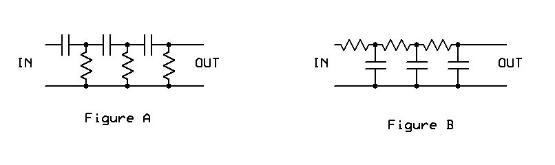
There are two types of phase shift networks used for phase shift oscillators. The one shown in figure A is usually used in oscillators where DC isolation between the output and input to the active device is required such as tubes, or transistors. The network shown in figure B is useful when used with an op-amp as the resistors provide DC feedback from output to the inverting input to the op-amp. The phase output of figure A leads the input, the phase output of figure B lags the input. With all of the various RC values used in an oscillator such as this, not every stage provides 60 degrees phase shift, but the cumulative phase shift of all 3 networks adds up to 180 degrees at he oscillation frequency.
To provide a mechanical analogy for an electrical phase shift stage, example figure B will be the easiest. First some rough equivalencies: Shaft rotation-voltage, the faster the rotation the higher the voltage, torque-current, the greater the torque the higher the current. For this analogy the input will be a shaft driving a slip clutch which in turn will drive a flywheel. The slip clutch will represent the resistor and will limit the torque applied to the flywheel(current). The flywheel will represent the capacitor. If the input shaft is rotated CW and then CCW this will represent an AC input signal. The flywheel will resist any speed change and will cause the slip clutch to limit the torque input. The torque, while limited will cause the flywheel to move but lag behind the shaft input(phase shift).
