When the house was being built I strung a length of # 12 house wire along the ridge beams the full length of the roof. It leads down to a terminal on the wall over my work bench on the second floor. The antenna wire is now covered with insulation and sheet rock. Its not as efficient as it would be if it were in free air but it works. I will not be transmitting on it with any great power, maybe QRP if I ever learn the code. A second terminal is connected to a #2 cable leading down to the crawl space and connected to an 8 foot ground rod, There is also a counterpoise wire laying on the bare earth and under the vapor barrier and connected to the ground rod. This antenna /ground system shows resonance at 2.45 Mhz it also shows a 50 ohm VSWR (wish wash) of 1.2 at 27.6 Mhz, Probably the two story ground lead, I could use the ground for a CB antenna.
5/8 wave 6 meter antenna. The literature says a 5/8 wave antenna is better than a 1/4 wave because it has a lower radiation angle and does not spray all of the signal upward. Any thing greater than a 5/8 wave and the pattern breaks up into many lobes and performs worse than a 5/8 wave. I made up an 11 foot vertical out of one inch copper pipe and mounted it in the back of the Ford F450 flat bed. The bottom rests in a ABS pipe plug to keep it in place and insulate it from the steel truck bed. It is held upright with 4 guy ropes. It will be set up after arriving at the place where it will be used, I will not drive with it upright. A 5/8 antenna is not resonant so a small inductor is used in series with the co-ax center conductor to make the antenna think it is a 3/4 wave. I started the coil with about 3′ of #12 house wire wound on a broom handle. I had way too many turns, it showed resonance at 12 Mhz and an input impedance of 1 or 2 ohms. No wonder the 40 and 80 meter boys and girls have a tough time driving a short whip on their cars. I stated to remove turns from the coil and as the resonant frequency went up the impedance also went up. When I reached 52.525 Mhz the antenna looked like 50 ohms and the VSWR was 1. I wonder if this works on all bands. I have not had a transmitter on this antenna yet because I do not have the wiring in the truck that will handle the current. I will not try it out in town because many neighbors have TV antennas with amplifiers and a 6 meter signal would wipe them out. I will stick to 2 meters. design your own 5/8 wave vertical antenna More info: May 1970 73 Magazine page 36
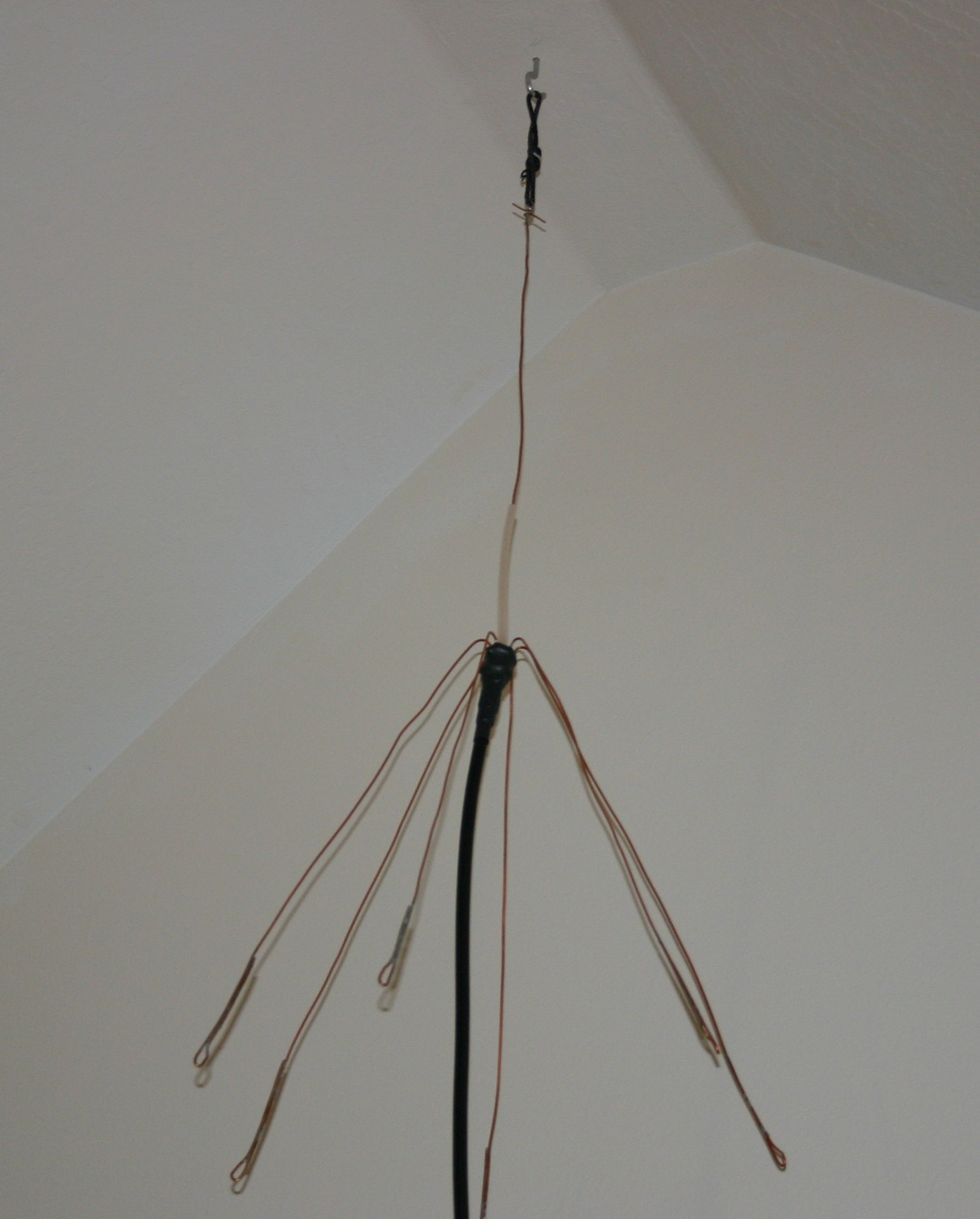
1/4 wave 2 meter antenna. I needed a 2 meter antenna for indoor use in my work room. First I tried a sleeve decoupled antenna made with a piece of RG213 with the center conductor as the driven element and a 1/2 copper pipe 19″ long over the outside of the co-ax with the shield soldered to it. I have seen this antenna recommend for use as an emergency or portable antenna usually with the shield pulled down over the outside of the co-ax to act as a decoupling sleeve. I could not get the VSWR very low and every time I moved or touched the co-ax the VSWR moved all over the place. Maybe a larger sleeve would work better. At this point I decided to build another antenna with drooping ground wires. I again used RG213. The shield was cut away leaving 19 in. of center conductor exposed. A loop was made at the end so a piece of cord could be passed through to hang it to a hook in the ceiling. About a 1/2 inch of shield was retained when it was stripped from the center conductor. Some heat shrink tube was placed over the co-ax just below the point where the remaining shield exited. The heat shrink tubing protected the co-ax from soldering heat and also provided a tight fit for a 1″ long piece of 1/2″ copper tubing which was slipped over the co-ax below the shield exit point. This piece of copper tube provided a solid point to which the shield and the ground plane wires could be soldered. 8 wires 19″ long and the co-ax shield were soldered to the copper tube. The ground plane wires were spaced evenly around the tube and covered with heat shrink to hide the ugly solder job. A small loop was made in the end of every ground wire so I would not get a poke in the eye when I got under the antenna to tune it. I did not tune the antenna in the usual manner of changing the driven element length for minimum VSWR. I used a MFJ-259 antenna analyzer to tune to resonance. The driven element came out to less than 18″ probably because I left about 6″ of insulation on the center conductor (driven element) and made the element look electrically longer. After much cutting the driven element came out too short so I added a short piece of #14 solid wire to the top to load it a bit. It resonated at 146.13 with no more changes The ground wires were shortened also providing a sharper resonance point. The ground plane wires were then bent away from the co-ax until the meter gave a minimum VSWR reading. Moving the co-ax or touching the outside does not change the VSWR so the ground plane must have gotten rid of all the RF on the shield. The VSWR at 146.13 is not measureable and the highest is at 144 and is below 1.2. I can now get into two repeaters. See the picture below.
3/4/2015 New Long Wire Dipole
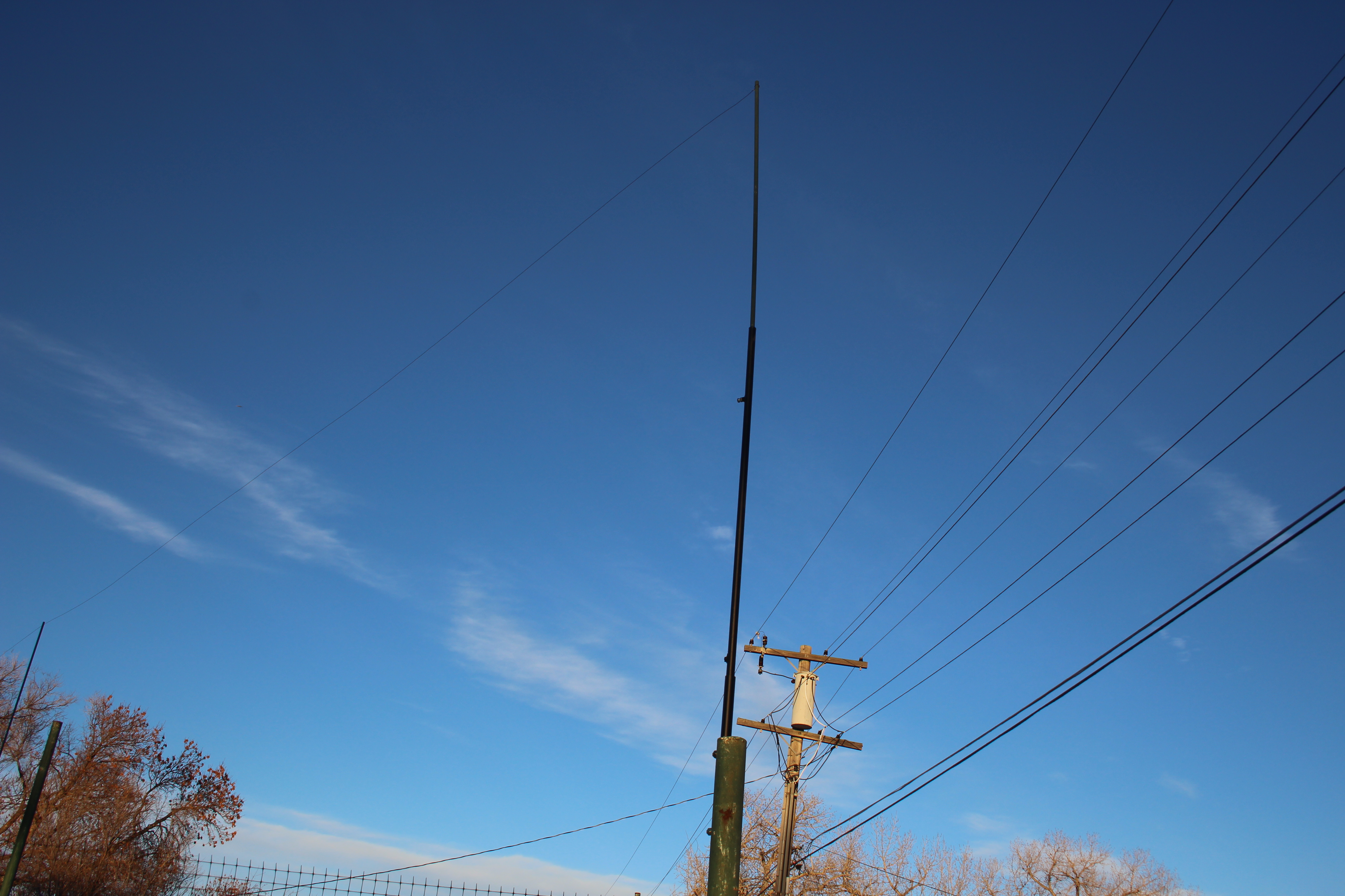
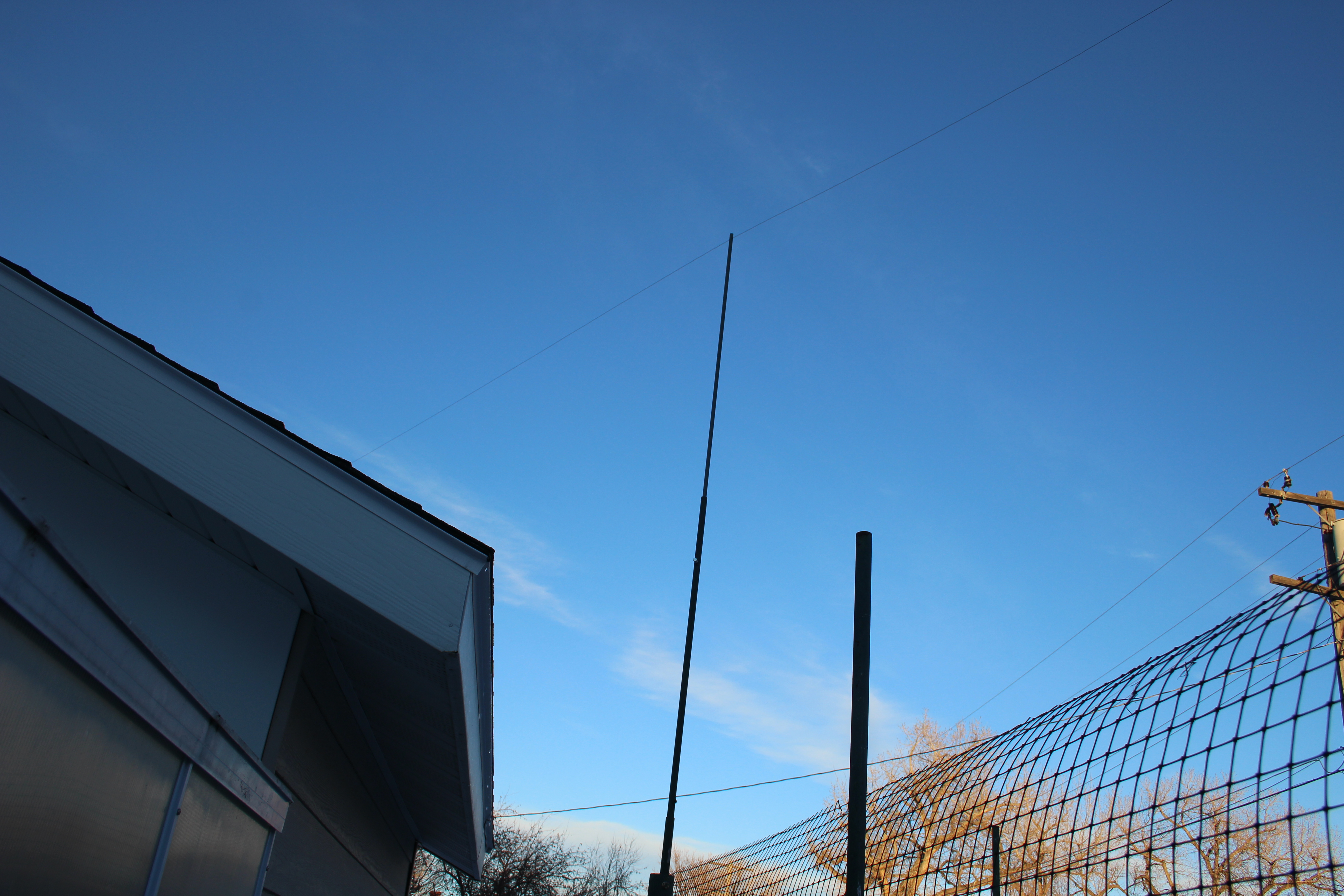
A new antenna was installed several months ago. I now have a long wire dipole installed over an old garage and over our garden patch. I do not know its exact length but it is resonant at 2Mc. The antenna has slightly uneven lengths on either side of the feed point and an angle of around 20 degrees with the apex at the feed point. The leg lengths and the slight V were not for any electrical reason, but were dictated by the position of support points. The antenna runs roughly East and West. I thought I might be able to talk to some old friends in California on this antenna with its orientation broad side to the North and South, but I can’t. I am still a tech and until I get my general ticket I am limited to a 200Kc slot on 10 meters. The antenna has so many wave lengths at 10 meters all of the signal sprays off the ends and nothing broadside. I have good coverage to Japan, Hawaii, and the East coast but not a peep from CA,NV,AZ, or anything to the South. If I listen to 17 meters and below, I start to hear stations to the South.
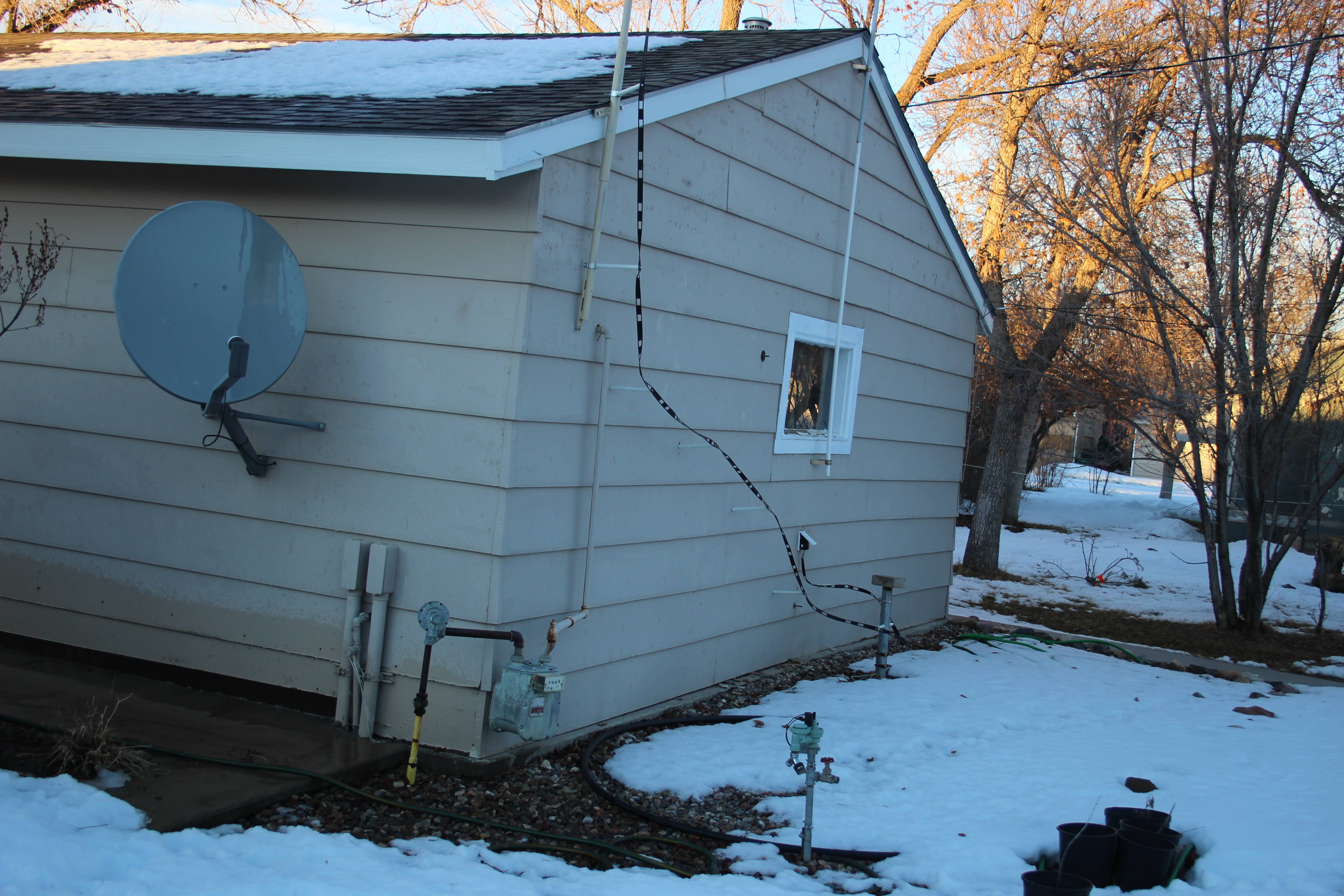
The antenna is made from copper weld wire with over 500 lb pull strength. A fiberglass ladder line dipole junction from MFJ supports the ladder line at the feed point. I did not know if the fiberglass junction block would hold together on an antenna of this size after being exposed sun light so I placed an electric fence compression insulator at the feed point and hung the MFJ block below it on wires from the insulator, the MFJ block now only supports the ladder line. The supports for the antenna are 10 foot long fiberglass poles. The fiberglass poles are 7/8th inch in diameter and are sold as tree stakes. The poles are flexible and are very good insulators. The fiberglass poles are inserted 2 feet into 8 foot long pipes 1 inch in diameter and locked in place with 1/2in bolts threaded through the side of the pipe. The 1in pipe is reinforced by 2 feet of 1.25in pipe where the support pipes attach to the roof eaves or attach to posts in the garden. Each half of the dipole is supported at its mid point by a fiberglass pole. The East end by a garden fence pole and the West end by a TV antenna tripod in the center of the roof on the old garage. The feed point of the antenna is brought into the garage by 50 feet of ladder line. The ladder line is spaced away from the support pole and supported by 8 inch spacers made from ¾ inch fiberglass tree stakes. The ladder line snakes around an unused well casing which will someday have a lightning arrester and then through a 50amp plug and into an outdoor weather proof socket. This probably not the best RF practice, but permits unplugging the antenna when a storm is due. More ladder line inside the garage carries the signal from the weather proof socket to a 4:1 Palomar BA-4 balun. The balun connects to a MFJ 927 auto tuner and then through 185 feet of LMR400 coax run through underground conduit into the house and up to my work room/shack. At one time I thought I might run a vertical against an earth ground with a 10 foot run to a ground. Because this would be an imperfect ground, I added two sets of Palomar sleeve ferrites to the LMR400 at the garage end to keep RF local. This essentially gives me a 1:1 balun into the auto tuner and 4:1 balun out of the tuner. It does not seem to bother anything. I measured the loss of the 185 feet of LMR400 to be 1db at 30Mc and 2db at 60Mc. The electrical ¼ wavelength of the LMR400 run seems to be around 1Mc, I shorted the garage end and looked at it with an antenna analyzer. The analyzer showed alternate dead shorts and 500 ohms at 1Mc intervals. The analyzer only goes down to 1.8Mc so I do not know what the actual electrical ¼ wavelength is. I am too lazy to build a bridge and check it with a function generator. There was no need to do this check on the feed line, I did this check just to see what I could see and because I could. I got lucky, with all of the mismatches and long feed lines I get a good match on 10 meters without a tuner. The match looks fair on 6 meters, but the band is dead so I don’t know if it works up there or not. Come June or July I should know. I have not yet added the relay and antenna amplifier to bring LW and AM broadcast into the house on a run of RG-6.